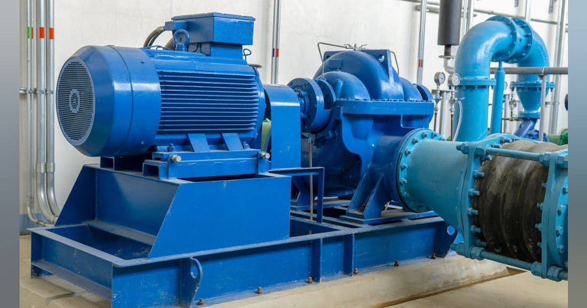
When applied to large, highly capacitive rotating machinery, the use of a resonating inductor may be required to extend the charging current capability of the test equipment. This effectively helps overcome what might otherwise be a limiting factor to attaining the recommended test voltage.
Performing power factor tests at the same voltage every time the test is performed over the life of each specific apparatus allows results to be trended and compared in such a way as to differentiate between gradual changes and those that might be considered more significant. Gradual changes often relate to a normal aging process; more significant changes can result from unusual stresses to the insulation. A good analogy would be a person who grows old gracefully as opposed to someone who falls and is injured. Being able to identify changes as well as the severity of those changes can provide predictive insight into preventing unplanned downtime and/or impending failure.
Power factor tip-up tests
While power factor testing applies to almost any type of electrical insulation, power factor tip-up tests are especially applicable to dry-type insulation such as that found in some smaller distribution transformers as well as in rotating machinery. Performing power factor testing on motor windings can serve as a baseline measurement for trending purposes over time. A power factor tip-up test shows the variation of dielectric losses over a range of voltages and is widely used to identify and even sometimes characterize voltage dependencies in winding insulation.
More specifically, excluding outside influences, an oil- or liquid-filled apparatus is expected to maintain the value of dielectric losses throughout the range of voltages up to and including the rated line to neutral voltage. However, solid/dry insulation has proven to be more voltage-dependent due to the nature of these materials, even within the rated line-to-neutral range of operation. A great deal of information regarding this topic is available in the IEEE Std. 286-2000, IEEE Recommended Practice for Measurement of Power Factor Tip-Up of Electric Machinery Stator Coil Insulation.
To better understand the value of power factor tip-up, let’s define what it is and how it can complement a standard power factor test. The electrical power industry offers the following definition of power factor tip-up from IEEE 100, The Authoritative Dictionary of IEEE Standards Terms, Seventh Edition.
“The difference between power factor measurements at two different designated voltages applied to an insulation system, other conditions being constant.
- The first power factor measurement is often conducted at approximately 25% of the rated line-to-neutral voltage. This should be a low enough voltage that partial discharge has not yet begun to occur.
- A second power factor measurement is performed at 100% of the rated line-to-neutral voltage.”
Since solid/dry type insulating materials are proven to be more voltage-dependent than other types of insulation, it is much more likely that partial discharge will begin to occur, producing increased losses and higher values of power factor. This is where power factor tip-up testing becomes a more valuable indicator regarding the health of the insulation.


